News center
Share
【概要描述】Solid oxide fuel cells (SOFCs) and reversible solid oxide electrolysis cells (SOECs) offer high conversion efficiency and broad fuel adaptability, enabling distributed combined heat and power generati
【概要描述】Solid oxide fuel cells (SOFCs) and reversible solid oxide electrolysis cells (SOECs) offer high conversion efficiency and broad fuel adaptability, enabling distributed combined heat and power generati
Solid oxide fuel cells (SOFCs) and reversible solid oxide electrolysis cells (SOECs) offer high conversion efficiency and broad fuel adaptability, enabling distributed combined heat and power generation and high-temperature hydrogen production by electrolysis. They are regarded as highly promising energy-conversion technologies in the hydrogen-energy sector. Commercialization is mainly based on two structural routes: tubular and planar. Planar SOFCs provide higher power density and convenient stack expansion, making them a major technology route being pursued by companies in China and abroad.
Planar SOFCs normally operate at temperatures of 600–850°C and are exposed to severe thermal cycling caused by frequent start-up and shutdown. The mismatched coefficients of thermal expansion among ceramic electrodes, metallic interconnects, and fastening bolts can readily cause fluctuations in sealing-surface pressure. As a mainstream gas-tight sealing solution for planar stacks, glass-ceramic seals are highly sensitive to compression load: insufficient pressure can cause fuel and air cross-leakage, while excessive pressure can crack the brittle PEN ceramic cells. Under these operating conditions, disc springs (Belleville washers) are widely used as elastic compensation elements in the axial compression system of the stack to maintain stable sealing load and ensure long-term stack reliability.
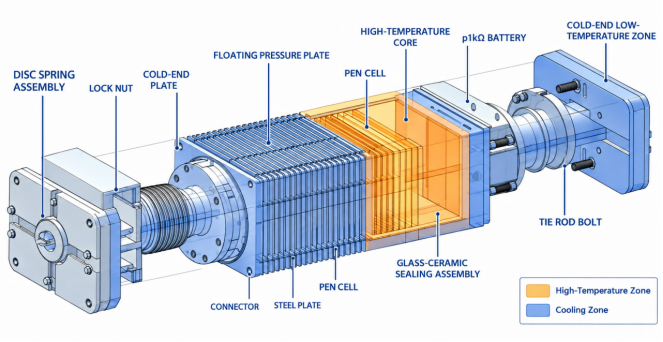
A complete planar SOFC stack can structurally be divided into two major modules: the high-temperature stack core inside the furnace and the cold-end compression mechanism outside the furnace. The high-temperature stack core contains PEN cells (anode–electrolyte–cathode), Crofer iron-chromium alloy interconnects, glass-ceramic seals, and conductive current-collecting layers, all continuously exposed to a high-temperature reaction environment. The external compression system consists of tie-rod bolts, end plates, insulating plates, floating compression plates, disc-spring assemblies, and locking nuts, with most components located in the low-temperature region.
A common misconception in engineering practice is to classify disc springs as sealing components. In fact, their functional boundaries are clear: the glass-ceramic seal is the core component responsible for gas tightness and preventing gas leakage, whereas Raleigh disc springs are elastic preloading and compensation elements. They do not provide gas-tight sealing themselves; instead, they continuously generate stable pressure to keep the sealing interface tightly engaged. Similar to an industrial flange system, the glass-ceramic seal is equivalent to the sealing gasket, while the disc spring supplies the continuous compression force for the gasket. Together, they complete the sealing function of the stack.
Early laboratory prototypes often used rigid bolts tightened directly. However, this arrangement is difficult to accommodate the extreme temperature differences encountered by SOFCs. As the stack heats from room temperature to its operating temperature, the ceramic, alloy, and fasteners undergo different amounts of axial expansion; during cooling, the entire assembly contracts. A rigid fastening structure cannot absorb these deformations, creating two critical risks: pressure rises sharply after thermal expansion, potentially cracking brittle ceramic cells; and preload decreases after cooling, allowing gaps to form in the seal. In addition, over tens of thousands of operating hours, stainless-steel tie rods can undergo continuous creep, causing the assembly load to gradually decrease. Because the effective operating window of glass seals is very narrow, rigid tightening alone cannot meet long-term service requirements. This is a key reason why disc-spring assemblies have become standard components in mass-produced stacks.
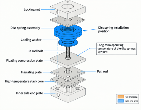
1. Standard Disc-Spring Assembly Layout and Design Guidelines
Mature mass-production designs generally place the disc springs in the cold-end compression structure of the stack, away from the high-temperature furnace zone. The standard axial assembly sequence (from outside to inside) is: tie-rod bolt → locking nut → disc-spring assembly → outer cold-end plate → insulating plate → floating compression plate → high-temperature stack core → inner floating compression plate → inner end plate. The disc springs are mounted on the tie rods, with the mainstream arrangement positioned between the locking nut and the outer end plate. In a small number of designs, the disc springs are placed between the end plate and the floating compression plate, but all designs follow the same mandatory requirement: control the long-term operating temperature of the disc springs to ≤250°C.
Conventional 50CrV4 and 60Si2Mn alloy spring-steel disc springs will experience significant creep when the long-term ambient temperature exceeds 300°C, resulting in rapid loss of elastic load and compensation capability. Therefore, they must not be placed inside the furnace. Only some space-constrained R&D prototypes use Inconel 718 nickel-based high-temperature alloy disc springs close to the high-temperature region; however, material and processing costs increase substantially, making this solution unsuitable for large-scale mass production. By contrast, tubular SOFCs rely on their tubular structure to achieve self-sealing and do not require large-area planar sealing structures. Their axial constant-pressure requirement is low, so disc springs are rarely used. Demand for disc springs is therefore highly concentrated in planar SOFCs and planar SOEC electrolysis stacks.
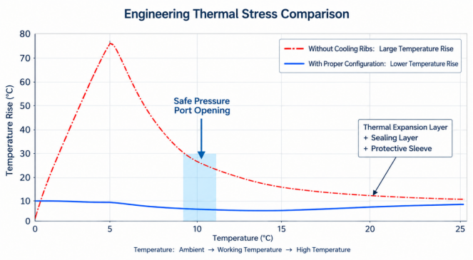
First, they compensate for thermal-expansion mismatch between dissimilar materials and absorb axial deformation. Throughout heating and cooling, differences in the expansion of ceramic PEN cells and metallic interconnects generate small axial displacements. Through elastic deformation of the conical disc shape, the disc springs absorb dimensional variations and keep the sealing-surface load within a safe operating window, avoiding sharp pressure fluctuations.
Second, they compensate for high-temperature creep of fasteners and reduce preload loss. SOFC stacks are designed for service lives of tens of thousands of hours. Under continuous high-temperature conditions, tie-rod bolts gradually relax. Disc springs continuously release stored elastic energy to compensate for load loss, reducing the probability of long-term leakage and improving the stack's start-stop cycle life.
Third, they provide flexible buffering and protect the brittle PEN ceramic substrate. PEN cells are brittle ceramic components with limited overload resistance. Disc springs form a flexible buffering mechanism that distributes thermal stress and eliminates stress concentrations caused by rigid tightening, effectively preventing compression fracture of the cells.
Fourth, they ensure the long-term gas-tight performance of glass-ceramic seals. The sealing performance of glass-ceramic seals depends strongly on uniform and stable surface pressure. Disc springs continuously maintain compression at the interface, preventing the seal from opening during thermal cycling and ensuring stack gas tightness and operational safety.
Considering installation temperature and load requirements, two mature material-selection systems can be adopted. For kW- and MW-class commercial SOFC stacks, when disc springs are located at the cold end and the long-term temperature is below 250°C, 50CrVA and 60Si2Mn alloy spring-steel disc springs are preferred. These materials provide good fatigue stability, high load consistency, and excellent cost performance, making them suitable for high-volume production and delivery.
For special prototypes with space constraints and short-term disc-spring temperatures above 350°C, Inconel 718 nickel-based high-temperature alloy disc springs can be selected. They provide excellent high-temperature creep resistance and serve as a high-end alternative. Phosphating or oxidation-protection coatings can also be applied to delay oxidation and relaxation during long-term exposure to the atmosphere.
Disc springs can be configured in different stacking arrangements to meet design requirements: series stacking (alternating orientation) increases total travel and is suitable for structures with large axial deformation; parallel stacking (same orientation) increases output load and meets high compression-force requirements; and compound stacking combines the characteristics of series and parallel arrangements for complex load requirements. During design, the maximum allowable compression must be calculated accurately to prevent the disc springs from being completely flattened and undergoing permanent plastic deformation. Engineers should verify the load-deflection curve against the stack assembly parameters to determine the optimum stacking configuration.
First, mass-production projects should prioritize an external cold-end disc-spring arrangement to eliminate the risk of high-temperature creep at the source. Second, disc-spring assemblies should be distributed evenly across multiple tie rods to ensure balanced end-plate loading and avoid uneven sealing pressure caused by local eccentric loading. Third, component classification should be standardized: in the BOM and technical documentation, disc springs should be defined as elastic compensation elements rather than sealing components. Fourth, the clearance between the tie rods and the disc-spring inner diameter should be properly matched, with sufficient guiding space reserved to prevent assembly jamming and ensure free expansion and contraction of the disc springs.
Thermal-expansion mismatch, bolt creep, and fluctuations in sealing load during high-temperature start-up and shutdown are key challenges that must be addressed in the structural design of planar SOFC stacks. With their compact structure and controllable load characteristics, disc springs provide dynamic compensation of sealing pressure across the full temperature range while protecting both glass-ceramic seals and brittle ceramic cells, significantly improving the reliability of stack thermal cycling. In engineering applications, designers should prioritize cold-end placement and select the appropriate disc-spring material and stacking configuration according to operating temperature and target preload.
As commercialization of solid oxide cell technology continues to accelerate, disc-spring assemblies specially developed for SOFC and SOEC operating conditions will become indispensable mechanical elastic components for optimizing stack structures and extending overall service life, helping solid oxide cell technology achieve large-scale commercial application more rapidly.